


Structural Design Of A 18m × 55m × 6m Steel Warehouse For Papua New Guinea With 5-Ton Overhead Crane
Project Overview
Location: Papua New Guinea (PNG)
Climate: Tropical; no snow, negligible seismic activity
Wind Speed: 120 km/h (≈33.3 m/s) → Basic wind pressure ≈ 0.7 kN/m² (per AS/NZS 1170.2 or local code equivalent)
Building Dimensions: Width: 18 m, Length: 55 m, Eave Height: 6 m
Roof Pitch: 5° (standard for drainage; rise ≈ 0.8 m at mid-span)
Wall & Roof Cladding: 0.45 mm pre-painted corrugated steel sheets (single skin)
Internal Equipment: One 5-ton electric overhead traveling crane (EOT), span ≈ 16.5 m, runway beams supported by main columns
Product Introduction
Structural Design of a 18m × 55m × 6m Steel Warehouse for Papua New Guinea with 5-Ton Overhead Crane, Roof Ventilators, and Skylights
1. Project Overview

Location: Papua New Guinea (PNG)
Climate: Tropical; no snow, negligible seismic activity
Wind Speed: 120 km/h (≈33.3 m/s) → Basic wind pressure ≈ 0.7 kN/m² (per AS/NZS 1170.2 or local code equivalent)
Building Dimensions:
Width: 18 m
Length: 55 m
Eave Height: 6 m
Roof Pitch: 5° (standard for drainage; rise ≈ 0.8 m at mid-span)
Wall & Roof Cladding: 0.45 mm pre-painted corrugated steel sheets (single skin)
Internal Equipment: One 5-ton electric overhead traveling crane (EOT), span ≈ 16.5 m, runway beams supported by main columns
2. Structural Layout
2.1 Primary Framing System
Main Frames: Rigid portal frames spaced at 7.86 m intervals (7 bays over 55 m length → 8 frames total, option will be 9 bays in 6.11m each bay).
Frame Configuration:
Columns: CBC customized H sections (welded plate sections)
Rafters: Tapered built-up I-sections
Base: Pinned or fixed base (fixed preferred for crane loads) embedded into reinforced concrete footings
Crane Runway System:
Crane runway beams: HEA/UB 300–350 (depending on deflection criteria)
Bracket connections welded to column flanges at ~5.5 m height
Crane rail: Standard QU70 or similar
Bracing: Horizontal and vertical bracing between runway beams
2.2 Secondary Members
Purlins: C-sections (C200×60×20×2.5 mm) @ 1.5 m spacing on roof
Girts: C-sections (C150×60×20×2.0 mm) @ 1.2 m vertical spacing on walls
Bracing System:
Roof: X-bracing in end bays + longitudinal bracing along ridge/eaves
Walls: Cross-bracing in gable ends and one side wall
All bracing: Ø12–16 mm steel rods or angle sections
2.3 Roof Accessories
Ventilators: Continuous ridge ventilator (polycarbonate or metal) – 55 m length
Skylights: Translucent FRP or polycarbonate panels integrated every 3rd purlin bay (~4.5 m spacing), covering ~10% of roof area → approx. 100 m²
2.4 Foundation
Reinforced concrete pad footings under each column (size estimated at 2.0 m × 2.0 m × 0.8 m deep, depending on soil bearing capacity ≥100 kPa)
3. Load Analysis & Structural Design Criteria
3.1 Loads (per AS/NZS 1170 series or AISC 360)
Dead Load (DL):
Roof cladding + purlins: 0.12 kN/m²
Crane girder + rail: 0.5 kN/m (line load on columns)
Live Load (LL): Maintenance load = 0.25 kN/m² (non-accessible roof)
Wind Load (WL):
Basic velocity pressure q = 0.613 × V² (V in m/s) → q ≈ 0.68 kN/m²
External pressure coefficients (Cp):
Windward wall: +0.7
Leeward wall: –0.5
Roof (5° slope): –0.9 (suction)
Internal pressure: ±0.2 (assumed partially open building)
Net design pressure ≈ 1.0–1.2 kN/m² (critical suction on roof)
Crane Load:
Vertical: 50 kN (5 t) + impact factor (25%) → 62.5 kN per wheel
Lateral: 10% of lifted load → 5 kN per wheel
Longitudinal: 5% braking force
3.2 Key Design Checks
Portal Frame: Designed for combined gravity + wind + crane loads using second-order analysis (P-Δ effects considered)
Deflection Limits:
Roof: L/180 under wind
Crane runway: L/600 under vertical load
Local Buckling: Web stiffeners at crane bracket locations
Connections: Welded moment connections at rafter–column joints; bolted splices for transport

4. Material Take-Off (MTO)
| Item | Description | Quantity | Unit Weight (kg/m) | Total Weight (kg) |
|---|---|---|---|---|
| Main Frames | Tapered I-sections (avg. 110 kg/m) | 8 frames × (2×6 m col + 18.5 m rafter) = 236 m | 110 | 25,960 |
| Crane Runway Beams | UB 356×171×51 (51 kg/m) | 2 × 55 m | 51 | 5,610 |
| Purlins | C200×2.5 mm | (55/1.5 +1) × 18 m ≈ 684 m | 3.2 | 2,189 |
| Wall Girts | C150×2.0 mm | 2×(55+18)×(6/1.2) ≈ 730 m | 2.3 | 1,679 |
| Bracing | Ø16 rod / L50×5 angles | ~400 m | 1.5 avg | 600 |
| Roof/Wall Sheets | 0.45 mm PPGL | Roof: 55×18.2 ≈ 1,001 m²; Walls: 2×(55+18)×6 = 876 m² | 4.5 kg/m² | 8,457 |
| Fasteners, Rails, Accessories | - | - | - | ~2,000 |
| Total Steel Weight | ≈46,495 kg |
Note: Excludes foundation rebar and concrete.
5. Design Adaptations for Other Regions
5.1 Philippines (Typhoon-Prone)
Wind Speed: Up to 250 km/h (e.g., Typhoon Haiyan) → q ≈ 3.0 kN/m²
Key Changes:
Increase main frame section sizes by 30–50%
Reduce portal frame spacing to 6 m (9 bays) for better load distribution
Use thicker cladding (0.55–0.60 mm) with enhanced fastening (closer screw spacing, storm clips)
Strengthen roof-to-frame connections (use cleats instead of straps)
Add more bracing (both transverse and longitudinal)
Higher safety factors in wind uplift design (especially at eaves and corners)
Consider double-skin insulated roof to reduce thermal stress and improve durability
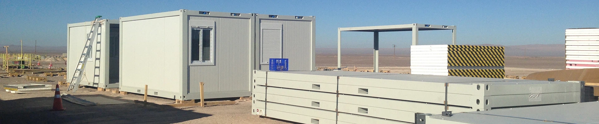
5.2 Chile (High Seismic Zone, e.g., Zone 4 per NCh433)
Seismic Coefficient: Sa(T) ≈ 0.6–0.9g (depending on soil and period)
Key Changes:
Switch from rigid portal frames to braced frames or moment-resisting frames with ductile detailing
Use uniform (non-tapered) H-sections to ensure plastic hinge formation control
Base plates designed for full moment + shear + uplift from seismic overturning
Crane supports must be seismically restrained (snubbers or lateral stops)
Roof diaphragm must act as rigid horizontal truss → closer purlin spacing (1.2 m) and stronger sheet fastening
Ductility class requirements per AISC 341 or local Chilean code (e.g., use of low-yield-point steel not permitted)
Foundations designed for high uplift and sliding resistance
Avoid brittle elements (e.g., thin rods); use structural angles or tubes for bracing
Note: In seismic zones, the crane itself may require special anchoring and damping provisions, which are unnecessary in PNG.

6. Conclusion
The proposed warehouse for Papua New Guinea is optimized for moderate wind loads and crane operation, using cost-effective tapered frames and light-gauge cladding. For typhoon-prone Philippines, robustness against extreme wind governs the design, while in seismic Chile, ductility, redundancy, and energy dissipation become paramount-leading to fundamentally different structural systems and material usage. Local building codes (NSCP for Philippines, NCh for Chile) must be strictly followed in each case.
You Might Also Like


Send Inquiry