


Structural Design, Material List And Quantity Estimation For Precast Concrete Slab Factory in Southern Manila, Philippines
The factory adopts a portal steel frame structure, which is light in weight, high in structural strength, good in seismic and wind resistance, and suitable for industrial factory buildings with large spans and light loads
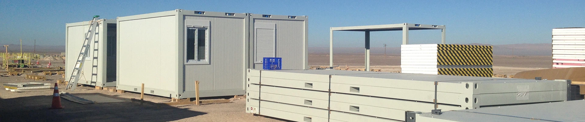
Product Introduction

Completion Time: The end of 2018
Dimension: Length 66m, Width 24m, Height 7.8m
Crane: 5-ton crane, height 5m (compliant with European standards)
Wind Load: 270kph
Seismic Grade: 8 degrees
Roof: 0.45mm color steel single sheet (no wall panels, no doors, no windows, no drainage system)
2. Structural Design
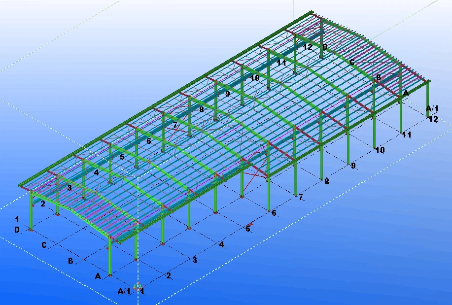
2.1 Main Structural System
The factory adopts a portal steel frame structure, which is light in weight, high in structural strength, good in seismic and wind resistance, and suitable for industrial factory buildings with large spans and light loads. The portal frame is composed of steel columns, steel beams, and purlins, which can effectively bear the roof load, wind load, seismic force and the load of the 5-ton crane.
2.2 Structural Design Highlights
Wind Resistance Design: Combined with the wind load of 270kph, the section size of steel columns and beams is optimized, and the connection nodes are strengthened to ensure that the structure can resist strong wind impact without deformation or damage.
Seismic Design: According to the 8-degree seismic grade, the structural layout is reasonable, the lateral stiffness of the frame is enhanced, and the ductility of the structure is improved to reduce the damage caused by earthquakes.
Crane Load Bearing: The steel beams and columns related to the crane are specially designed to bear the dead weight and working load of the 5-ton crane (height 5m, European standard), ensuring the safe operation of the crane.
Roof Structure: The roof adopts 0.45mm color steel single sheet, laid on the purlins, with simple structure and good waterproof performance; no wall panels, doors, windows and drainage system are set, which is consistent with the project requirements.

3. Material List and Quantity Estimation
All materials are selected in accordance with relevant national and European standards to ensure the quality and service life of the structure. The specific material list and quantity estimation are as follows:
|
Serial Number |
Material Name |
Specifications |
Quantity Estimation |
Remarks |
|
1 |
Steel Columns |
H-shaped steel, H300×250×6×10 |
About 20 tons |
Q355B, bearing main load, combined with seismic and wind load design |
|
2 |
Steel Beams |
H-shaped steel, H300×200×6×8 |
About 18 tons |
Q355B, portal frame beam, bearing roof load and crane load |
|
3 |
Purlins |
Z-shaped steel, Z180×70×20×2 |
About 10 tons |
Q235B, used to support roof color steel sheets |
|
4 |
Roof Color Steel Single Sheet |
0.45mm thick, galvanized + color coated |
About 1680㎡ |
Waterproof, corrosion-resistant, matching the roof structure |
|
5 |
Crane Rail |
QU70 |
About 68 meters |
European standard, matching 5-ton crane |
|
6 |
High-strength Bolts |
M20×80, 8.8 grade |
About 1200 pieces |
Used for connection of steel columns and beams |
|
7 |
Ordinary Bolts |
M16×50, 4.8 grade |
About 2800 pieces |
Used for connection of purlins and color steel sheets |
|
8 |
Steel Plate |
10mm thick |
About 8 tons |
Used for base plate of steel columns and connection nodes |
|
9 |
Anti-rust Paint |
Epoxy anti-rust paint |
About 1200kg |
For anti-rust treatment of steel structures |
3.1 Total Quantity Summary
Total steel consumption: About 60 tons; Total roof color steel sheet: About 1680㎡; Total bolts and other accessories: As shown in the table above. The quantity is an estimation based on the project parameters, and the actual quantity may have a small deviation according to the detailed construction drawing.
4. Supplementary Notes
The structural design complies with European standards (especially for the 5-ton crane) and local seismic and wind load requirements in the Philippines.
No wall panels, doors, windows or drainage system are included in the material list, which is consistent with the project requirements.
The material quantity is an estimated value, and the final quantity shall be subject to the detailed construction design drawing.

Part of the loading calculation as below(full calculation document as attached)
Load table under each single working condition
The column load
|
Working condition |
Column no. |
The load type |
The load value |
Load parameter 1 |
Load parameter 2 |
|
Left the wind 1 |
1 |
1 |
3.30 |
0.00 |
0.00 |
| 2 |
1 |
3.30 |
0.00 |
0.00 |
|
| 3 |
1 |
3.30 |
0.00 |
0.00 |
|
| 4 |
1 |
3.30 |
0.00 |
0.00 |
|
|
1 the right wind |
1 |
1 |
9.90 |
0.00 |
0.00 |
| 2 |
1 |
3.30 |
0.00 |
0.00 |
|
| 3 |
1 |
3.30 |
0.00 |
0.00 |
|
| 4 |
1 |
3.30 |
0.00 |
0.00 |
|
|
The left 2 wind |
1 |
1 |
3.30 |
0.00 |
0.00 |
| 2 |
1 |
3.30 |
0.00 |
0.00 |
|
| 3 |
1 |
3.30 |
0.00 |
0.00 |
|
| 4 |
1 |
3.30 |
0.00 |
0.00 |
|
|
2 the right wind |
1 |
1 |
9.90 |
0.00 |
0.00 |
| 2 |
1 |
3.30 |
0.00 |
0.00 |
|
| 3 |
1 |
3.30 |
0.00 |
0.00 |
|
| 4 |
1 |
3.30 |
0.00 |
0.00 |
Beam load
|
Working condition |
For several |
The number of load |
The load type |
The load value of 1 |
Load parameter 1 |
The load value 2 |
Load parameter 2 |
|
The constant load |
1 |
1 |
1 |
1.20 |
0.00 |
0.00 |
0.00 |
| 1 |
1 |
1 |
1.20 |
0.00 |
0.00 |
0.00 |
|
| 1 |
1 |
1 |
1.20 |
0.00 |
0.00 |
0.00 |
|
| 1 |
1 |
1 |
1.20 |
0.00 |
0.00 |
0.00 |
|
|
Live load |
1 |
1 |
1 |
1.80 |
0.00 |
0.00 |
0.00 |
| 1 |
1 |
1 |
1.80 |
0.00 |
0.00 |
0.00 |
|
| 1 |
1 |
1 |
1.80 |
0.00 |
0.00 |
0.00 |
|
| 1 |
1 |
1 |
1.80 |
0.00 |
0.00 |
0.00 |
|
|
Left the wind 1 |
1 |
1 |
1 |
7.92 |
0.00 |
0.00 |
0.00 |
| 1 |
1 |
1 |
7.92 |
0.00 |
0.00 |
0.00 |
|
| 1 |
1 |
1 |
6.60 |
0.00 |
0.00 |
0.00 |
|
| 1 |
1 |
1 |
6.60 |
0.00 |
0.00 |
0.00 |
|
|
1 the right wind |
1 |
1 |
1 |
6.60 |
0.00 |
0.00 |
0.00 |
| 1 |
1 |
1 |
6.60 |
0.00 |
0.00 |
0.00 |
|
| 1 |
1 |
1 |
3.30 |
0.00 |
0.00 |
0.00 |
|
| 1 |
1 |
1 |
6.60 |
0.00 |
0.00 |
0.00 |
|
|
The left 2 wind |
1 |
1 |
1 |
2.64 |
0.00 |
0.00 |
0.00 |
| 1 |
1 |
1 |
2.64 |
0.00 |
0.00 |
0.00 |
|
| 1 |
1 |
1 |
7.92 |
0.00 |
0.00 |
0.00 |
|
| 1 |
1 |
1 |
7.92 |
0.00 |
0.00 |
0.00 |
|
|
2 the right wind |
1 |
1 |
1 |
7.92 |
0.00 |
0.00 |
0.00 |
| 1 |
1 |
1 |
7.92 |
0.00 |
0.00 |
0.00 |
|
| 1 |
1 |
1 |
2.64 |
0.00 |
0.00 |
0.00 |
|
| 1 |
1 |
1 |
2.64 |
0.00 |
0.00 |
0.00 |
Crane 1
|
project |
node |
node |
|
Crane connection node number |
1 |
2 |
|
Vertical load of each node generated by the maximum wheel pressure on the left (Dmax is on the left of the span) |
181.430 |
56.390 |
|
Vertical load of each node generated by the maximum wheel pressure on the right (Dmax on the right) |
56.390 |
181.430 |
|
Vertical load of each node generated by the maximum wheel pressure of empty car on the left (Wmax is on the left of the span) |
0.000 |
0.000 |
|
Vertical load of each node generated by the maximum wheel pressure of empty car on the right side (Wmax is on the right side of the span) |
0.000 |
0.000 |
|
Vertical eccentricity between vertical load of crane and joints (m) |
0.500 |
0.500 |
|
Maximum horizontal force (Tmax) generated by horizontal brake force of crane at each node |
5.002 |
5.002 |
|
Vertical distance between transverse horizontal load of crane and each node (m) |
0.800 |
0.800 |
|
The effect adjustment coefficient considering space work and torsion effect |
1.000 |
|
|
Seismic shear force and increasing coefficient of bending moment caused by crane bridge |
1.000 |
|
|
Crane bridge weight |
141.221 |
|
|
Reduction coefficient of combined load of single span crane |
1.000 |
|
|
Reduction coefficient of combined load of two span cranes |
1.000 |
|

You Might Also Like


Send Inquiry